Valentino Ivan Wilson
Electromechanical Beverage Dispenser
Project Description:
My senior design project was a semester-long project funded by Cornelius Inc., a global leader in the beverage dispensing industry. Current beverage dispensers in the industry have outdated technology in desperate need of updating. The flow control valves in the beverage dispensers produced by Cornelius have been manual for decades, leading to issues in overall performance. These purely mechanical systems utilize a manually adjusted screw-spring-cylinder assembly to change the opening size of a set of orifices, which controls the volumetric flow rate of the fluid—syrup or carbonated water—in the dispensing line. These valves thus need to be adjusted for different types of drinks to accommodate each drink’s unique fluid properties. They also need to be adjusted for any environmentally induced fluid property change—such as temperature-induced viscosity changes. Additionally, these valves allow end-users of Cornelius beverage dispensers, such as restaurant owners, to decrease the proportion of syrup per drink dispensed for their economic advantage. My team was tasked with designing an electromechanical flow control system for Cornelius that can automatically control the volumetric flow rate in the dispensing lines regardless of syrup brand or the environment and be immune to human intervention. Additionally, based on the operating conditions inside Cornelius’ beverage dispensers and the expectations from the company, this new automatic flow control system needed to abide by the following criteria: 1) Have comparable dimensions with Cornelius’ current flow control system, 2) Withstand a nominal inlet pressure of 40-110 psi, 3) Withstand a shock pressure of 550 psi without catastrophic failure in case of water hammer, 4) Allow a maximum volumetric flow rate of at least 3.55 L/min (dispense 1 cup of drink within 4 seconds), 5) Control the volumetric flow rate within 1% of the set value in the steady-state, and 6) Last for 7-10 years.
My team consisted of five students. Aside from all group member administrative tasks, my role in the project was designing the overall mechanical system, prototyping the final device, and conducting all fluid dynamic analyses on the different valves of interest and the overall final design. I also served as project lead, interfacing between the different sub-groups within the group to ensure a final, cohesive device was produced.
Design Procedure:
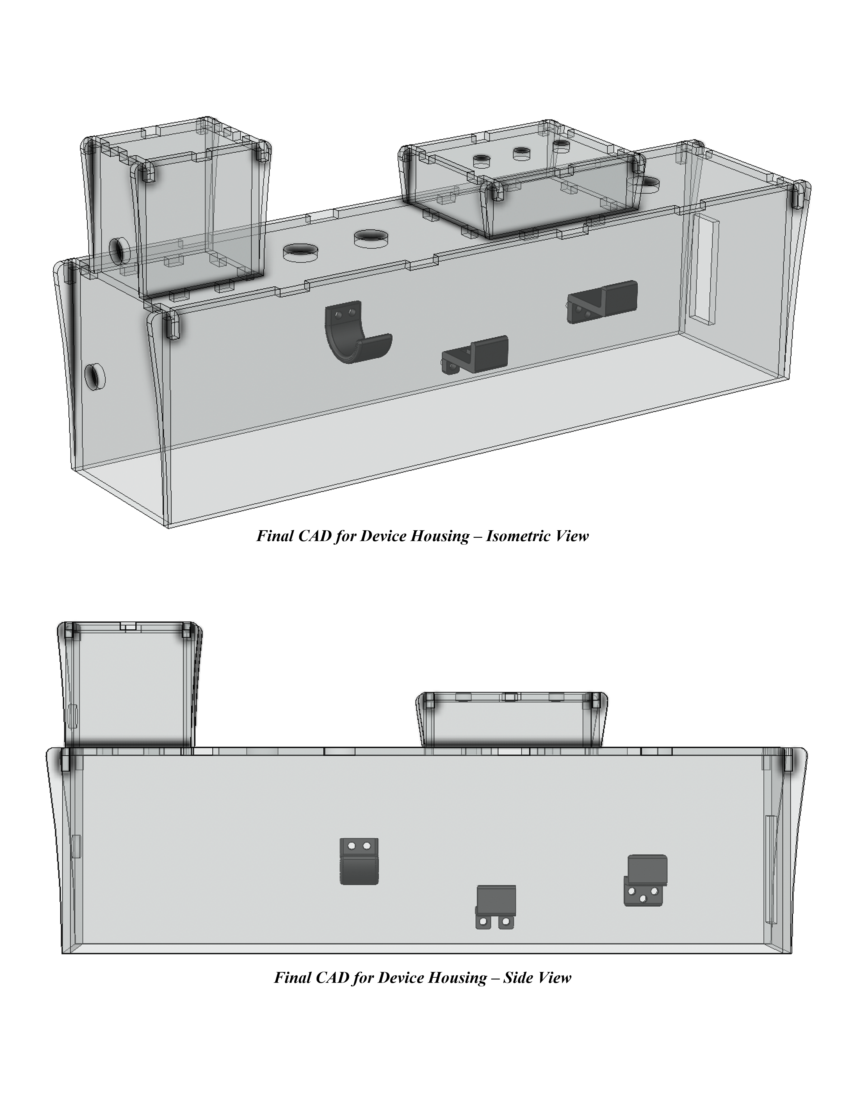
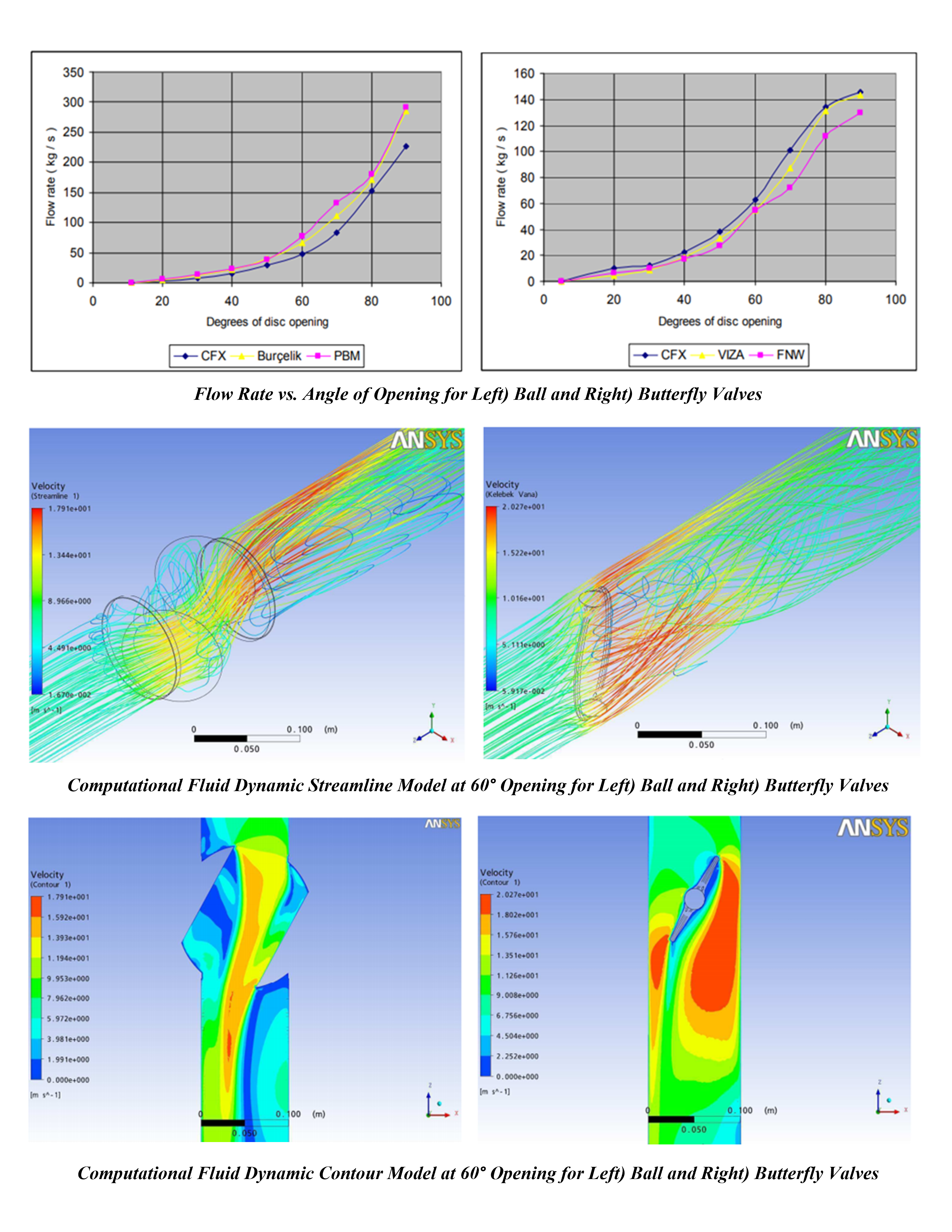
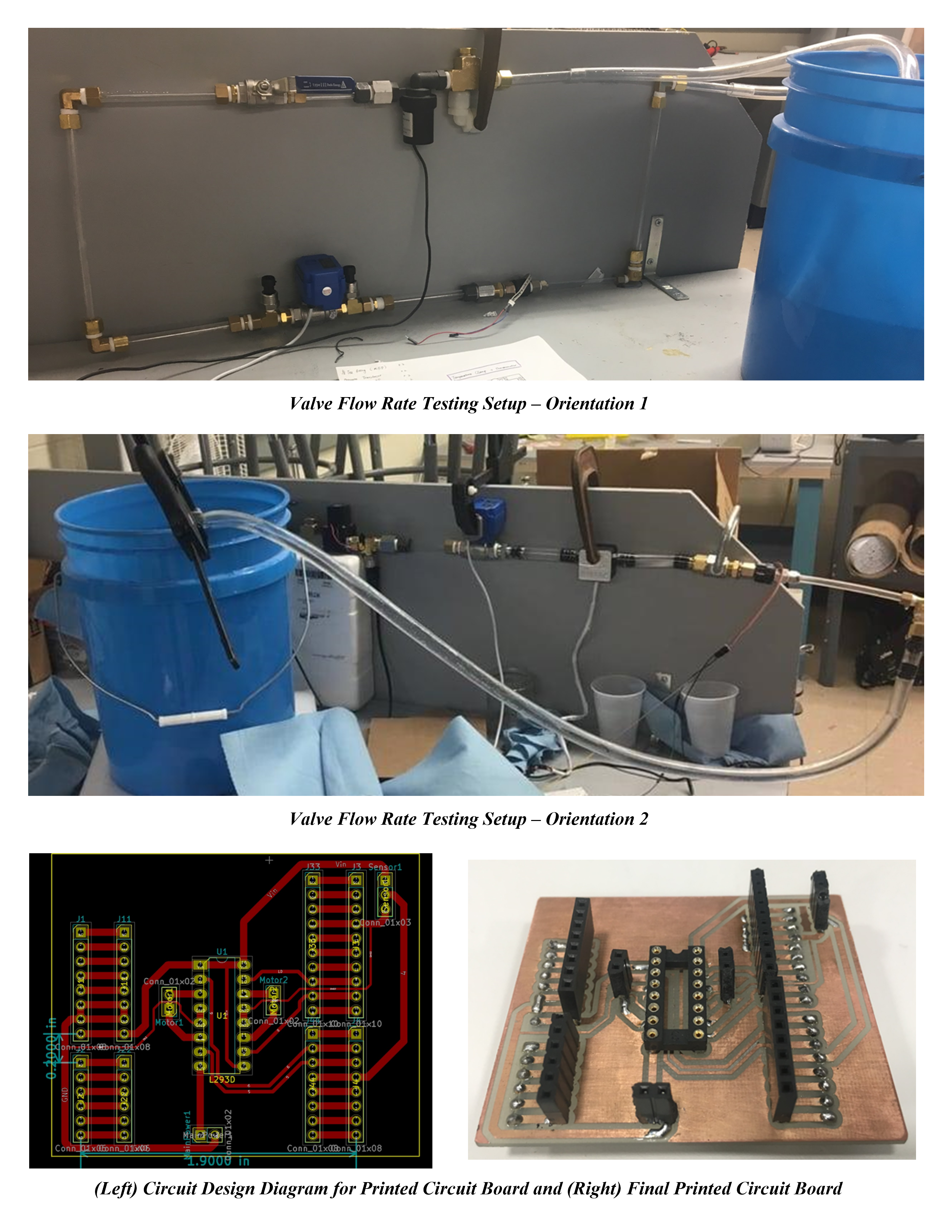
The team was divided into the mechanical and electrical sub-teams. I was named overall team lead and served as the head of both sub-teams to ensure project progress throughout the semester. Ideation for this project began with identifying the needs of our sponsor and learning the design and function of the current beverage dispensing systems. After understanding the current system’s inherent limitations, extensive literature reviews were conducted to understand the design requirements for the new electromechanical system. The literature review process encompassed valve designs (ball, globe, butterfly), fluid flow control systems, flow sensors, and fluid dynamic analyses. During this stage, I spearheaded the fluid dynamic analysis research and created mathematical models identifying the flow behavior of fluid through the different valves of interest under different conditions. After the literature review process, a patent search was conducted and standards were identified that needed to be met by our device. Once completed, my team identified possible design components and conducted a SWOT analysis to determine the final components. The mechanical team then worked to integrate the hardware of the system into one cohesive device while the electrical team worked on integrating the electronics and software for all components. SolidWorks was utilized for prototyping and a final working prototype was fabricated as a deliverable for the class. Extensive testing of our device was carried out and the results were analyzed and given to our sponsors as a final deliverable. My team was assigned a faculty advisor with whom we were required to consult weekly in order to identify possible directions for the project. Weekly meetings with our sponsor for project updates and project progress tracking were also required and taken out. Project progress was tracked through the usage of GANTT charts. Additionally, all materials purchased were recorded in a BOM to ensure our budget of $1000 was met. The project was completed with a comprehensive, in-depth document explaining how to create and use all components in the device.
Design Description:
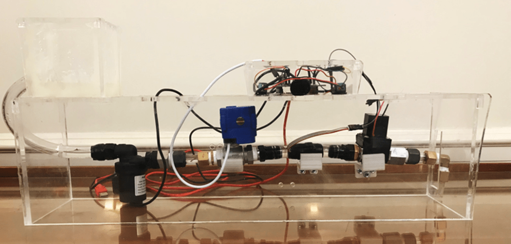
We developed an automatic flow control system consisting of a motorized ball valve, flow-meter, and microcontroller. The valve system was comprised of two components: the motorized ball valve and a solenoid on/off switch. Due to the usage of electromechanical components in the final system, motor wear was a large consideration in how the system will control the flow of the drink being dispensed. The team decided that having an all-in-one system where the valve opens to a certain angle for each beverage dispensed and then closes afterward would increase the wear on the motor and the 7-10 year lifespan requirement. Instead, we designed a two-component system. Each time a beverage is dispensed, the solenoid would be activated to allow the beverage to be dispensed. This system would reduce wear on the ball valve motor and ensure the beverage valve will last the 7-10 year lifespan. An oval gear flow meter was used for the syrup as it is a type of positive displacement flow meter that is suitable for high viscous and opaque fluids. To avoid unnecessary translation from mass to volume using the density of the fluid, a volumetric flow sensor was chosen to directly find the volume in real-time. The microcontroller implemented a closed-loop feedback proportional control law based on a sampling period of 200 ms for the motorized ball valve and 1000 ms for the flow meter. The control system converted the flow rate signal received from the flow meter to the voltage signal input to the motorized ball valve, eliminating the error between the sensed flow rate and the set flow rate. Meanwhile, the flow meter also outputted data for real-time system monitoring. The main goal of the control system was to regulate the current flow rate in the valve. With standard proportional control, this was easily achievable in the stable range of the valve opening, however, the hardware posed a challenge in the unstable range. At this range, the flow rate reacted more sensitively to small changes in the valve opening angle and resulted in a large error. To overcome this issue without changing the hardware, a control algorithm utilizing asynchronized communication was implemented. This meant the sensor and valve were activated in an alternating sequence and not simultaneously. In this design, only the sensor was activated until the flow reached steady-state and the corresponding datapoint was gathered. The sensor was then deactivated and the last datapoint from the sensor was used to send a proportional control signal to the valve. Based on this signal, the valve was now separately activated to make the required change in angle and turned off after 0.5 seconds. The sensor then turned back on and the process was repeated until the error in flow rate came within the desired range.
University:
University of Illinois at Urbana-Champaign
Program:
B.S. in Mechanical Science and Engineering
Course:
ME 470: Senior Design Project
Experience Level:
Senior Year
Project Duration:
4 Months

Valentino Ivan Wilson
Chicago, IL
