Valentino Ivan Wilson
Manual Car Transmission
Project Description:
This group project tasked us with creating a three-speed plus reverse manual transmission. Our transmission needed output speeds that were low, medium, and high relative to each other. The transmission also required that the speeds were changed with a single stick while the system was receiving input power (the system could not be turned off before switching gears). All input power for the transmission was transferred from a rotating input shaft perpendicular to the output shaft via a pulley. The overall transmission design could only occupy a width x length x height volume of 1’ x 1’ x 2’. My group consisted of five students and my role in the project, aside from normal group member tasks, was creating all CAD models, GD&T engineering drawings, and the final CAD assembly. All CAD was completed in SolidWorks. I was also responsible for all 3D printing of components.
Design Procedure:
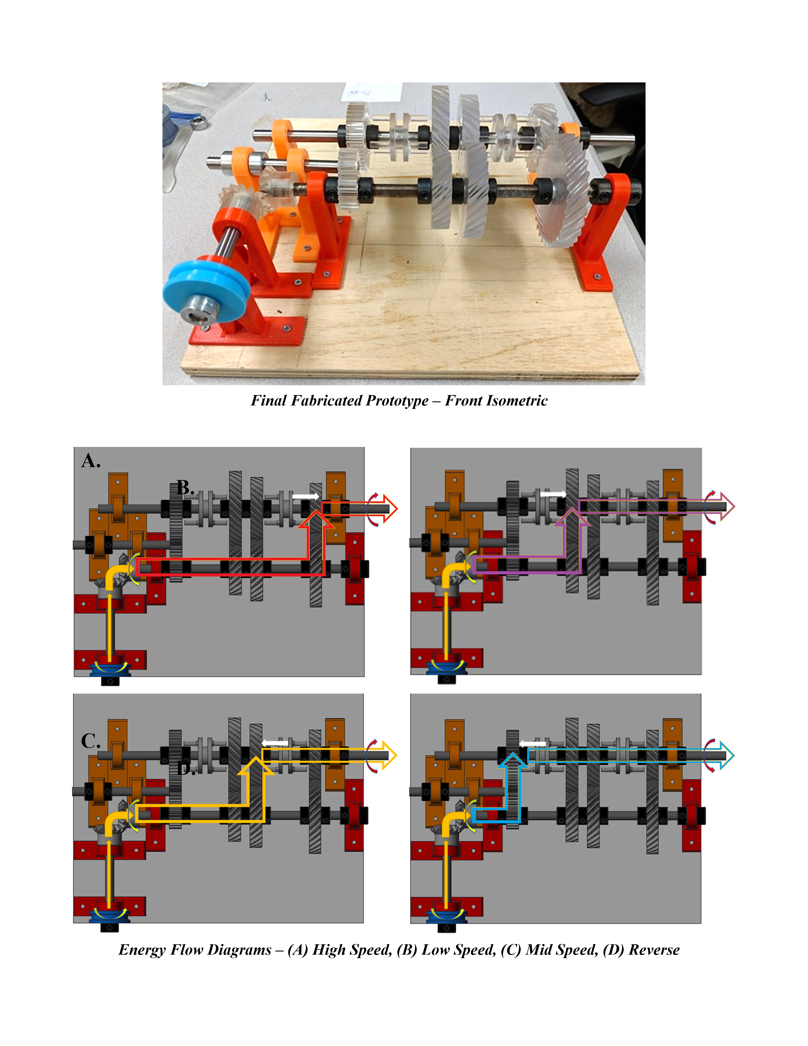
The ideation stage of our project consisted of each member developing design sketches which were evaluated with a SWOT analysis. Specific portions of each design were then combined to create our final working prototype design in CAD. Fabrication of the working prototype was completed using manufacturing methods available by the university. We utilized the Ford Rapid Prototyping Lab to 3D print all gears used in the transmission. All gears were made from Waterclear Ultra 10122 resin, which exhibited superior strength over PLA plastic. The resin material experienced less friction with the shafts and the SLA printing method allowed for greater precision when generating smaller features, such as the angled teeth on the helical gears. After our working prototype was created, a set of deliverable documents including energy transfer diagrams (of each speed in our transmission) as well as a force analysis, stress analysis, failure analysis, and Finite Element Analysis (FEA) of the bevel gears in our transmission. Project progress throughout the semester was documented through the usage of a GANTT chart and a final BOM was compiled with all expenditures for the project to ensure that our budget of $100 was not surpassed.
Design Description:
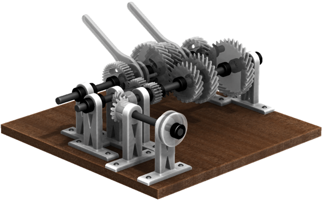
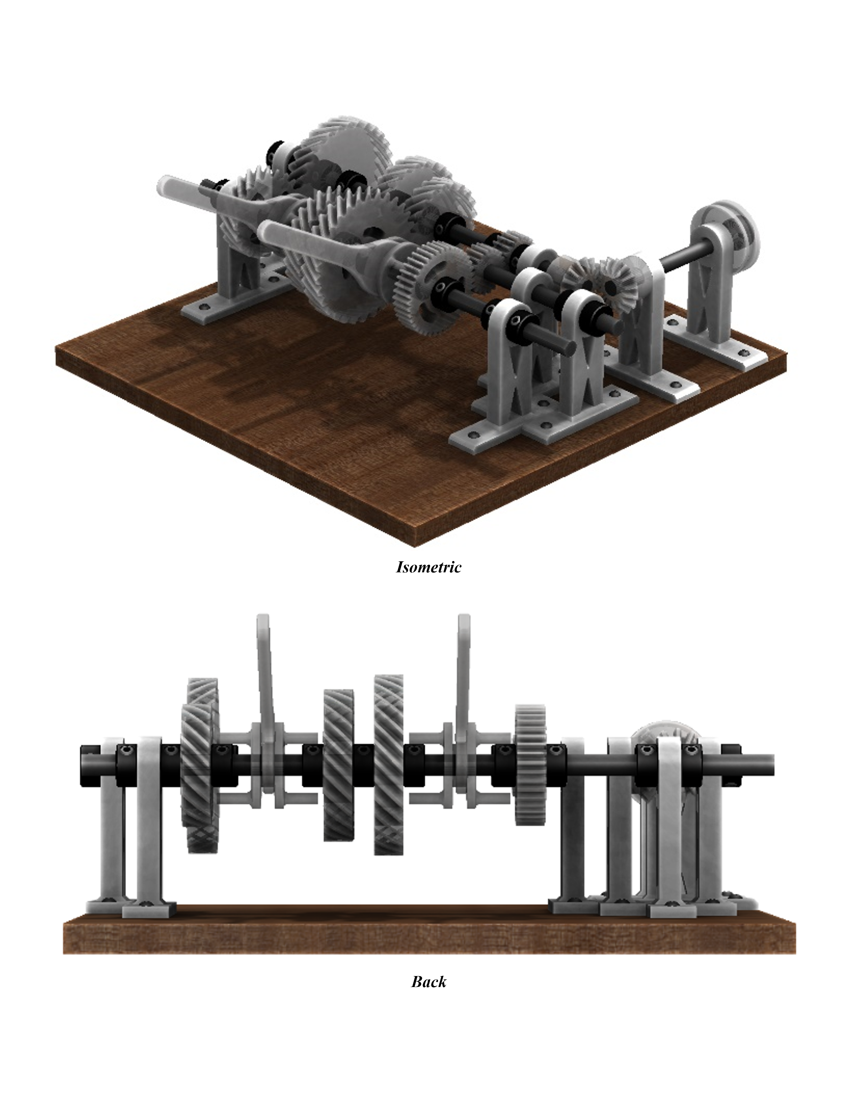
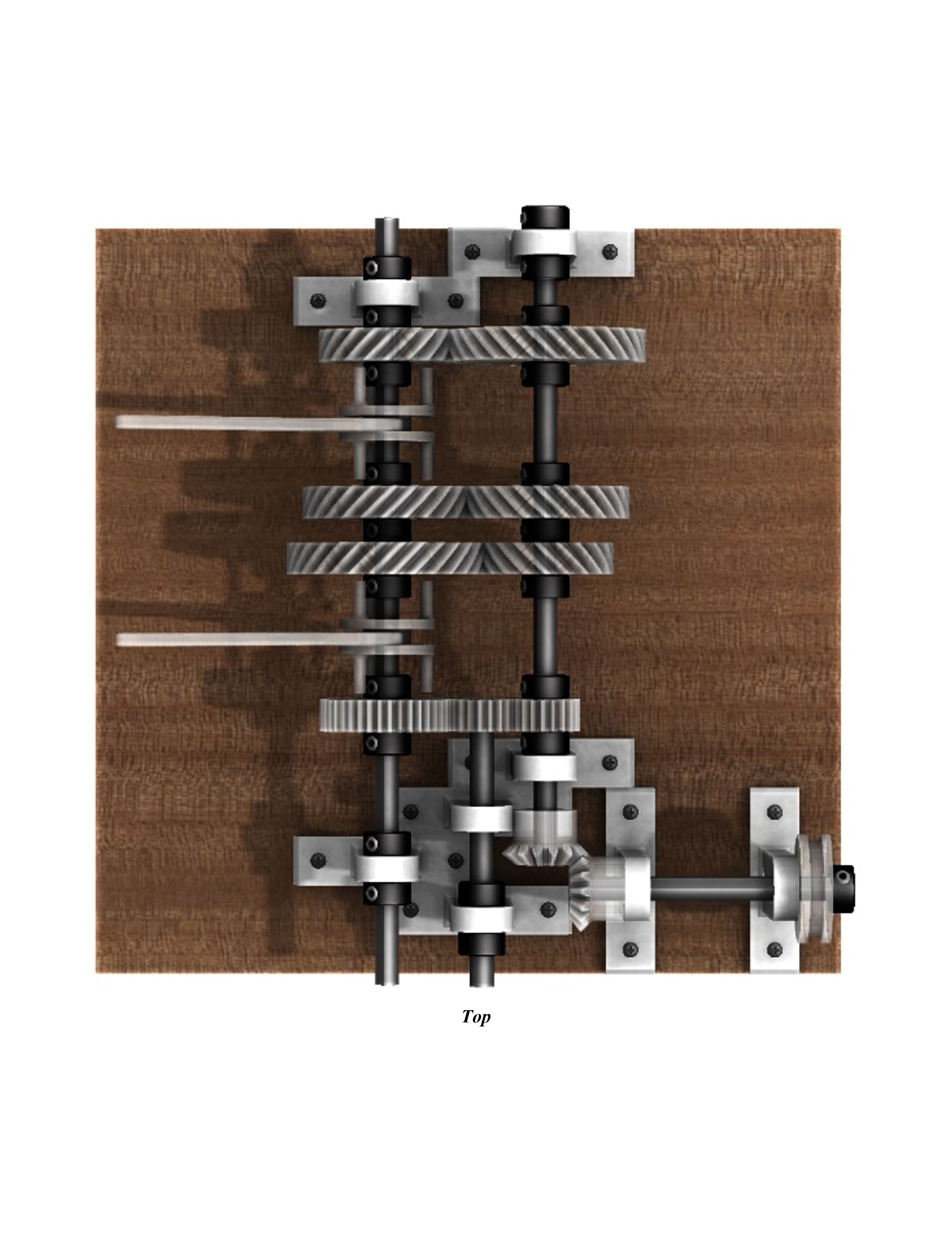
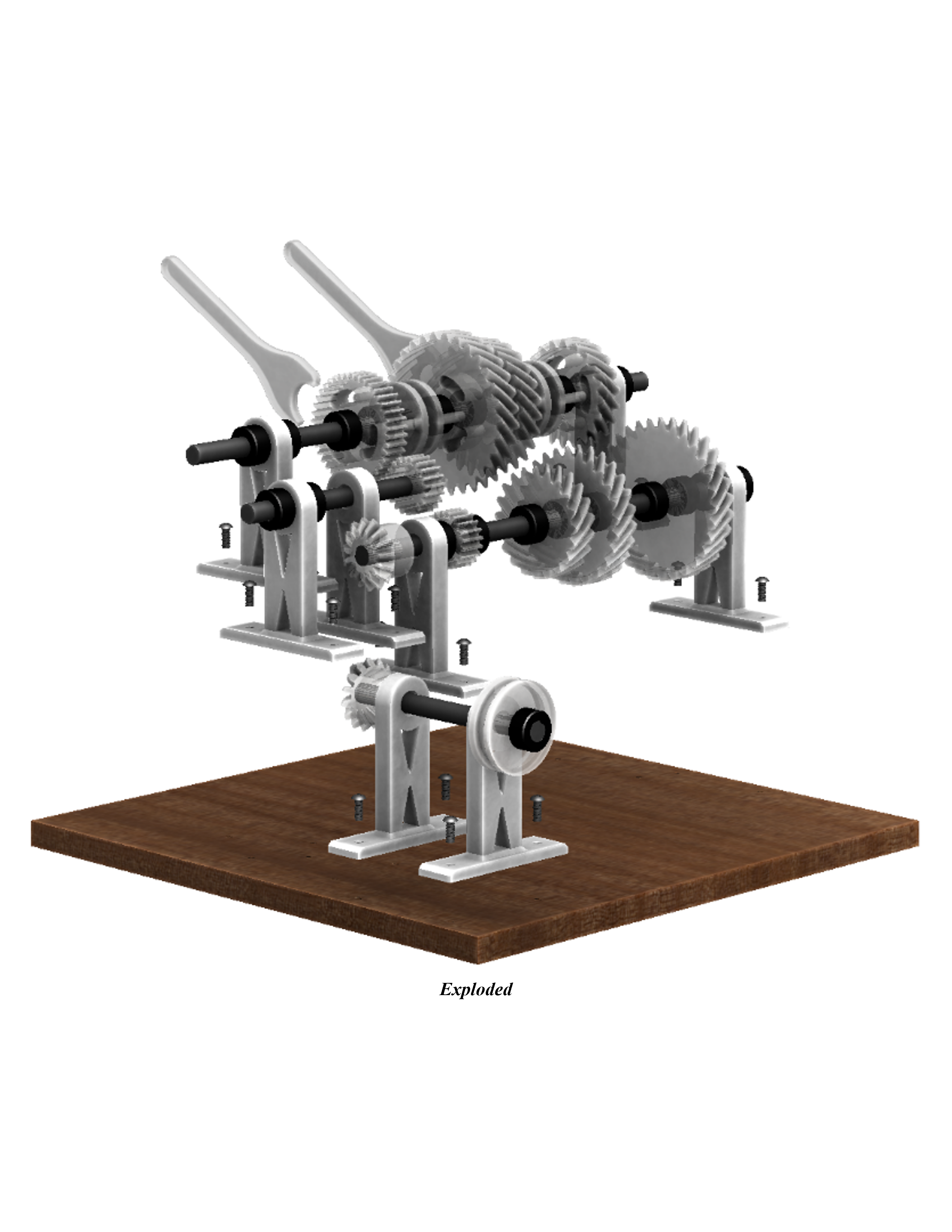
We developed a system that utilized bevel, spur, and helical gears to obtain the three-speed plus reverse transmission functionality. Our transmission utilized four separate shafts: input, output, countershaft, and reverse. These shafts were made from ⅜” d-shafts and were held in place by stands made of PLA plastic which were then affixed to the wooden base by wood screws. The transmission used a constant mesh design so that the non-engaged gears can rotate freely. The reverse shaft used an idle gear to reverse the rotation of the output shaft. Power was first transferred to the input shaft via a pulley which then transmitted the power across a 90° angle to the countershaft using bevel gears. The countershaft carried four gears: a spur gear for reverse, a small gear, a medium-sized gear, and a large gear with d-shaft profiles that affix them to the shaft. These gears were constantly engaged with freely rotating gears on the output shaft, forming a 1:2 gear ratio for reverse, 2:3 gear ratio for low speed, 3:2 gear ratio for high speed, and 1:1 gear ratio for medium speed. Two shaft sleeves were positioned on the output shaft which allowed for output speed selection while power was continuously being inputted. Reverse, low, medium, and high speeds were selected by engaging the shaft sleeves with the gears on the output shaft.
University:
University of Illinois at Urbana-Champaign
Program:
B.S. in Mechanical Science and Engineering
Course:
ME 371: Mechanical Design II
Experience Level:
Senior Year
Project Duration:
4 Months
Valentino Ivan Wilson
Chicago, IL
