Valentino Ivan Wilson
Nerve Visualizer
Project Description:
My graduate capstone project was a year-long project funded by Neurovision Medical Products, a biotechnology company focused on developing and marketing intraoperative monitoring technologies for the identification and preservation of motor nerves. Their mission is to provide leading-edge neuromonitoring surgical tools that empower clinicians to improve patient outcomes. A common issue with surgical procedures is the inability to accurately identify nervous tissue location intraoperatively, which oftentimes leads to nerve damage. In most cases, an accident leading to nerve damage results in lifelong complications for the patient including loss of sensation in the damaged area, chronic neuropathy, and muscular atrophy. Not only is locating the nervous tissue difficult for the surgeon, but also differentiating the nervous tissue from other tissue types such as connective tissue or blood vessels. Currently, surgeons rely on their anatomical knowledge, blunt dissection techniques, and intraoperative neuroimaging combined with preoperative visualization (MRI, ultrasonography, and OCT) to locate nerves during surgeries. The issue with these methods comes two-fold: there is not only a lack of real-time imaging with these techniques but also the peripheral nervous system varies highly between patients. It is quite impossible for surgeons to know exactly what they are seeing in every patient based on the information in a textbook or a prior scan that may be dated due to the body’s natural tendency to constantly change. For this reason, these techniques have oftentimes resulted in surgeons accidentally severing or damaging a patient’s nervous tissue which drastically alters their lives forever with a plethora of further complications down the road.
At the time, Neurovision had already produced a piece of equipment that used electrical impulses to determine the location of nerves. This piece of equipment is called the Nerveana Nerve Locator, which uses a nerve stimulator and EMG monitor to continuously stimulate soft tissues. The EMG monitor constantly detects, interprets, and records muscular responses. When an EMG signal of an evoked nerve is found, an alarm sounds to the surgeon providing them with the information that a nerve is nearby. This allows the surgeon to have a better idea of where peripheral nervous tissue is located, which ultimately allows for greater safety of the patient. The only drawback with this type of technology, however, is it lacks real-time imaging capability. My team was tasked with developing a handheld, OR-ready device for real-time, label-free detection of nervous tissue without patient-device contact and that used simple components capable of sterilization. Additionally, our design needed to abide by the following criteria: 1) have a user-centered design focused on being handheld and easy to use, 2) use polarized LED light for nerve detection, 3) contain electronic components to control the device, 4) capable of being coupled with fiber optics for use in endoscopic procedures.
My team consisted of three students. Aside from all group member administrative tasks, my role in the project was as design lead, creating all designs for the devices and all associated CAD. Additionally, I was named project lead, ensuring all tasks were completed and the project remained on track for successful completion by the deadline.
Design Procedure:
The ideation stage of the project began by identifying the needs of our sponsor and understanding the working principle of the Nerveana Nerve Locator system. Once the system was understood and our sponsor’s needs were addressed, the ideation process led directly into the literature review process where we conducted an in-depth analysis of the work conducted by Dr. Cha (a Neurovision associate and Institute for Pediatric Surgical Innovation researcher that is regarded as the expert in real-time nerve visualization). His work defined the primary mechanism for light polarization and how it can be applied to nerve visualization through the usage of Collimated Polarized Light Imaging (CPLi). His team determined that nerve cells contained an extreme aspect ratio resulting in strong anisotropic interactions with polarized light as oriented microtubules within the nerve cells reflect the collimated polarized incident light. The light reflection intensity is dependent on the orientation of the polarizers with respect to the microtubules. When the microtubules are at 45 degrees with respect to the light, the nerve cells give a strong white reflection. On the other hand, when the microtubules are at 90 degrees with respect to the light, the nerve cells become transparent. When these two behaviors are combined, the nerves produce a flicker allowing for the nervous tissue to be identified. This information played a crucial role in the design of the polarizing units created for this application. By using this information, we planned to design two different polarizing units that would be capable of producing incident light that could reflect off of nervous tissue, therefore making the identification of the nerves by the human eye possible. Before identifying the specifications of the two devices, my team conducted a patent search to identify if this or any related technology had been patented. We found a similar device called Illumivein that is used to detect veins in real-time to better help the IV insertion process. While this application was for veins, none were discovered for nervous tissue and therefore my team proceeded with determining the design components for the two polarizing units. To do this, my team conducted d a SWOT analysis followed by a Pugh matrix to refine the designs. I was then responsible for creating CAD models for both designs using SolidWorks. Weekly meetings with our sponsor for project updates and project progress tracking were also required and taken out. Project progress was tracked through the usage of GANTT charts.
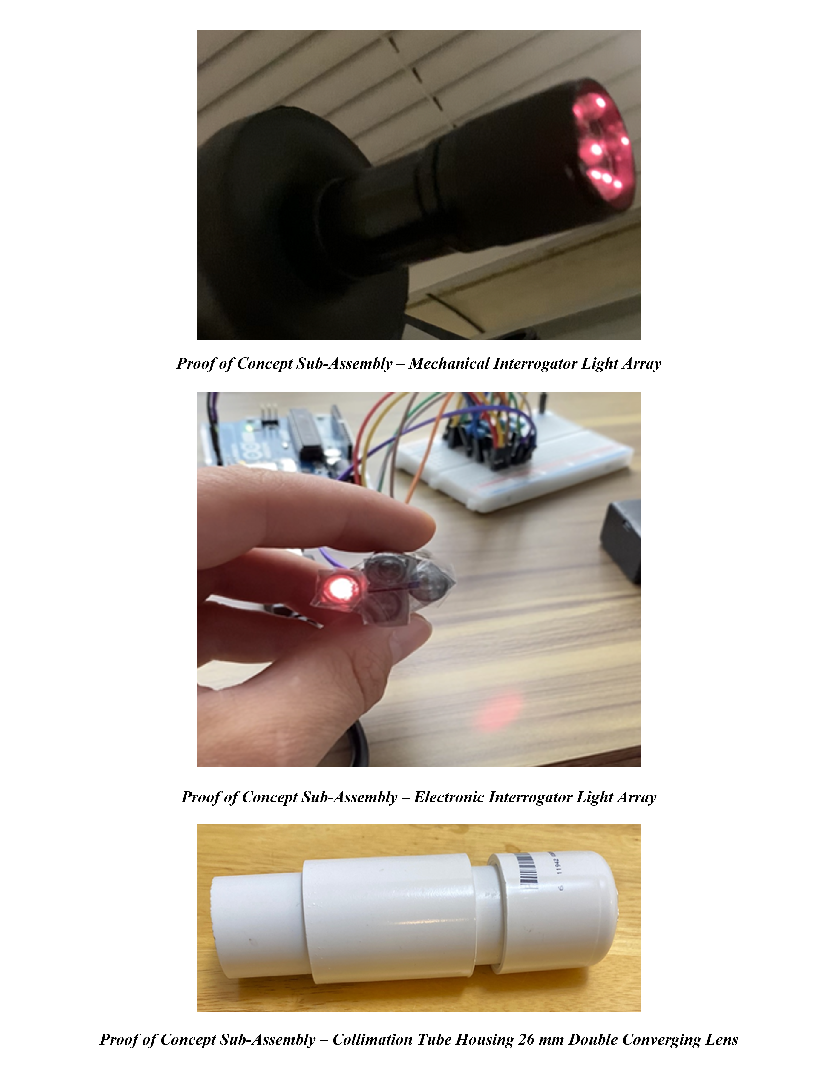
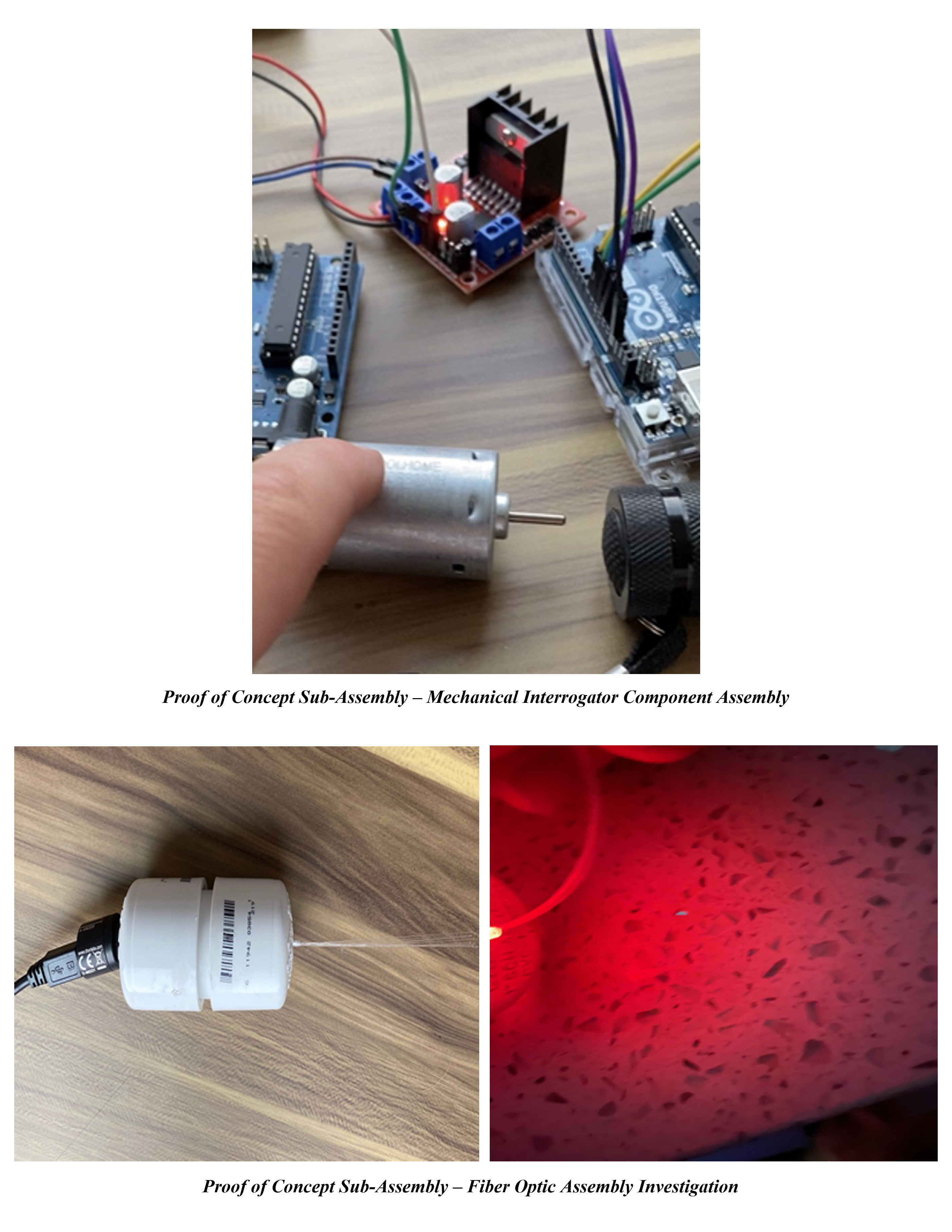
Due to the COVID-19 outbreak occurring during this period of time, we were unable to conduct the final assembly of the devices. Instead, CAD models for each design were developed and rough prototypes of their subassemblies were fabricated. The subassembly prototypes were tested and shown to be successful proofs of concept. The necessary code and wiring diagrams to run all electronic components were developed and documented. Comprehensive standard operating procedures and assembly directions for the devices were produced and documented as well. My team ensured that after the culmination of the pandemic, Neurovision would only need to manufacture the individual components from the CAD models, follow the detailed assembly instructions for device assembly and commence extensive testing.
Design Description:
Based on Neurovision’s needs, my team designed two collimated, polarized LED light interrogator systems for Neurovision, to be a part of their future nerve detection systems. Our light interrogator system came in two designs: mechanical and electronic interrogators. While each system consisted of different components and had different operating principles, they both utilized a collimated, polarized LED light array to exploit the nervous tissue’s anisotropic properties with light for nerve detection. Both interrogator designs used 780 nm Near-Infrared (NIR) LEDs for proper skin depth penetration. The light polarization was produced using P200A polarizing film and the collimation was taken out through the usage of a standard 26mm double-convex converging lens. Additionally, they both used an Arduino Uno to control all electronic components and a 9V battery as a power source. Aside from these components, the designs differed greatly in order to accomplish their intended functions
The mechanical interrogator was initially chosen for investigation since its working principle was most closely related to that of which was found in the literature review process. The light within the system would be polarized, collimated, and rotated in a circular fashion to induce the flickering effect of the nerve cells. Aside from the shared components aforementioned, the mechanical interrogator design consisted of LEDs, a mini DC motor, a motor driver module, a flashlight, a collimating lens, polarizing film, and specific attachments and connectors necessary for final assembly. The light array consisted of 5 LEDs retrofitted into a flashlight that rotated via a mini DC motor. The rotating light then shone through a stationary collimating lens and polarized film oriented at one angle to produce the desired nervous tissue response. An L298N motor driver module was used to control the speed and direction of the motor. A PWM signal was used to drive the DC motor which allowed for its speed to be controlled by increasing or decreasing the duty cycle.
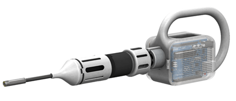
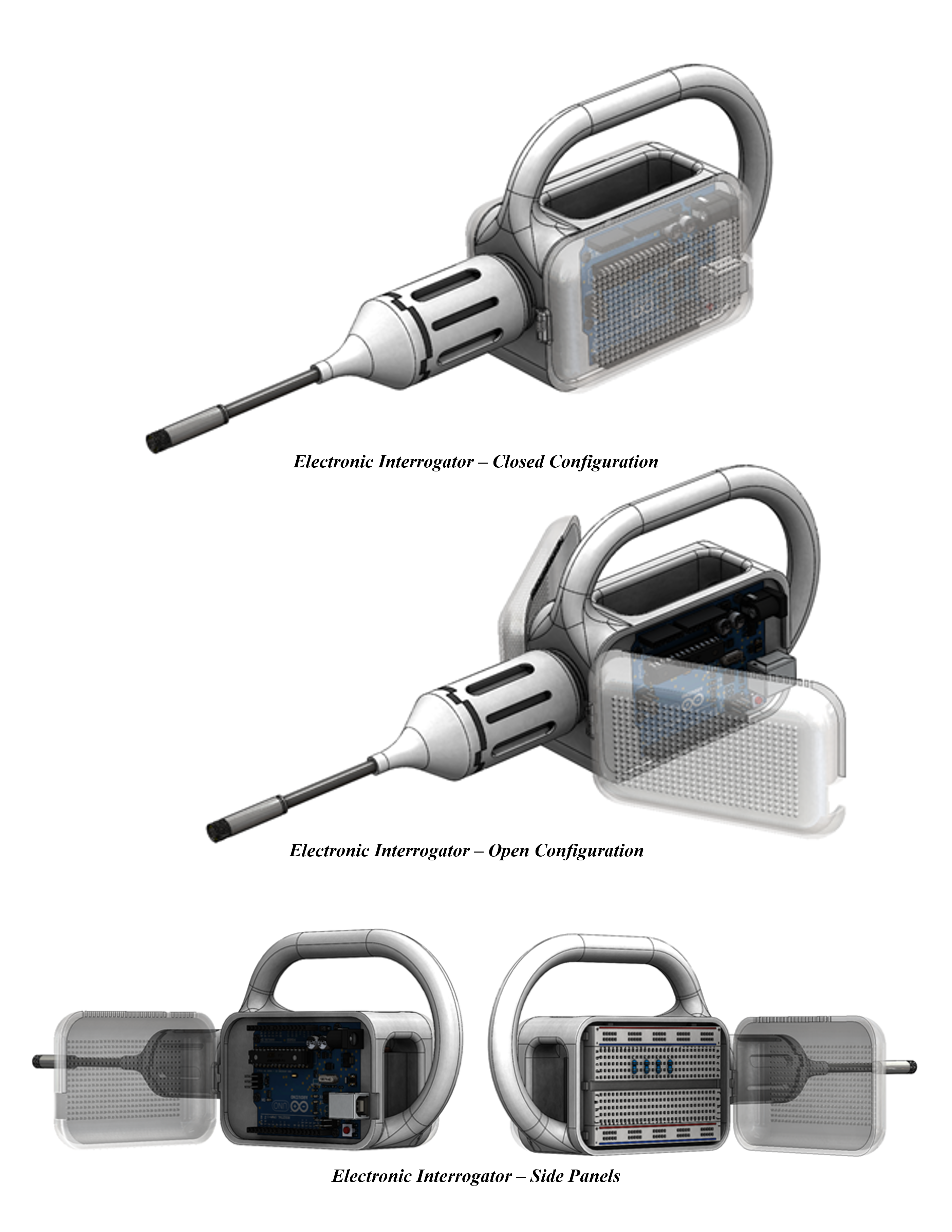
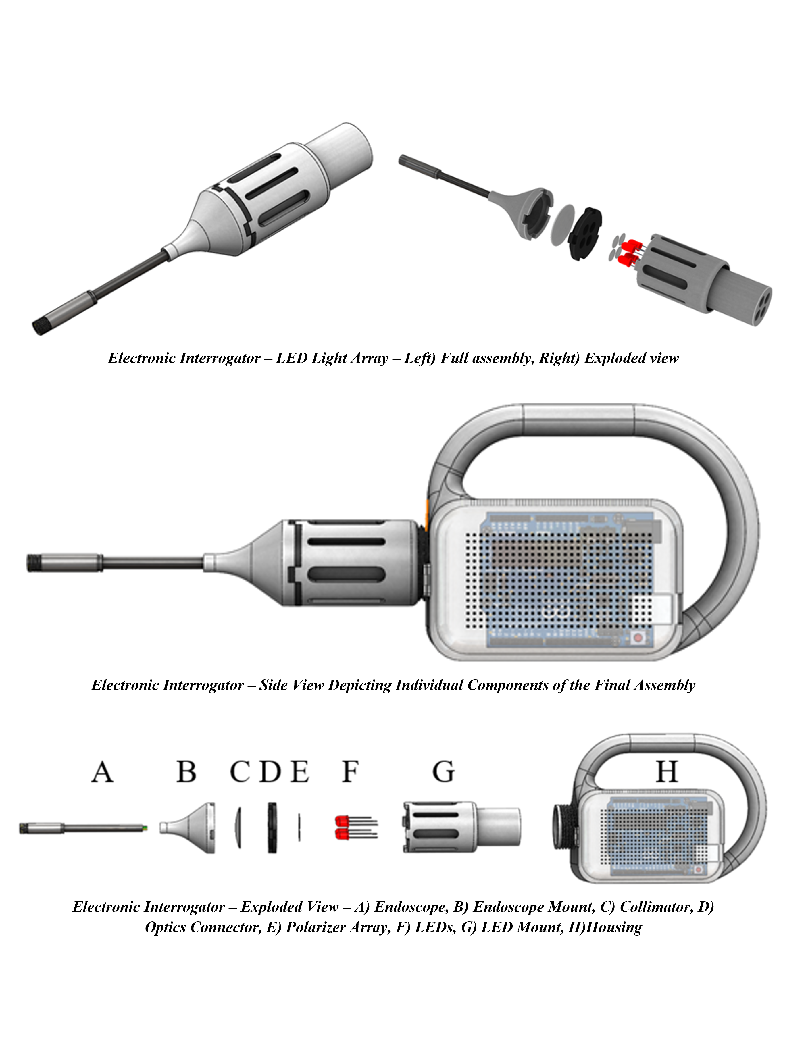
The electronic interrogator was the primary interest of our sponsor as it was purely theoretical before this project and had never been prototyped or tested before. Aside from the shared components aforementioned, the electronic interrogator design consisted of LEDs, a collimating lens, polarizing film, a breadboard, and specific attachments and connectors necessary for the final assembly. Each LED was also attached to a breadboard housed in the device with 50-80 ohm resistors to prevent burnout and overheating. The light array within the electronic interrogator consisted of an LED mount attachment, an optics connector, and an endoscope attachment. The LED mount consisted of four internal tunnels that spanned the diameter of the LEDs used. The diameters of these tunnels were an important consideration to ensure that no ambient light entered the system affecting the resulting incident light emitted from the device. Within each LED mount tunnel, a single LED was fixed to prevent any movement when the device was held at different orientations during operation. The LED mount was then mated to the optics connector via a press-fit connection which housed the polarizing film and collimating lens. The optics connector also contained the four tunnels found within the LED mount which allowed for four circular polarizing films to be cutout and fixed at different polarization orientations (0, 45, 90, and 135 degrees). The LEDs within the tunnels in the device would blink in a circular fashion thus emitting the illusion of rotation. This ‘rotation’ was caused by not only the sequential blinking of the LEDs but also the light passing through the different polarization orientations. The light would then emit from the device and induce the flickering of the nerve cells. Again, like the mechanical interrogator, the electronic interrogator could function with or without the endoscope attachment. If the endoscope were needed, the endoscope attachment would mate with the optics connector via a press-fit connection. This endoscope attachment was the same between device designs and functioned similarly as well.
The housing for both interrogators was designed to be handheld, cordless, and contain all necessary components for proper device function. All housing components for both the mechanical and electronic interrogators were designed to be 3D printed for ease of assembly. Each device contained two side panels containing all electronic components. Each panel rested on a hinge, allowing for easy access to the electronic components in the case of troubleshooting. Since the Arduino and other electronic components could have the possibility of overheating, holes were cut into each of the side panels to allow for heat dissipation. At the top of each panel, holes were cut for the wires of the electronic components to be routed into the negative space located centrally within the device. This negative space was intentionally placed to provide a place for all electrical wires to be housed without interrupting the aesthetics or function of the device. Specific connectors were designed and developed to help assemble the individual components of the interrogator. A final attachment was also created to adapt the device for usage with an endoscope. This attachment essentially reduced the diameter of the light from the size of the light source to the size of the endoscope. The device itself can function with or without the usage of the endoscope attachment, however, an attachment was created to integrate the usage of the fiber optics investigated. If fiber optics were to be integrated with the device, we determined that a bow tie fiber optic cable would be used as it allows the light’s unique polarity to be maintained throughout its length.
University:
University of Illinois at Urbana-Champaign
Program:
M.Eng. in Bioengineering
Course:
BIOE 575: Capstone Project
Experience Level:
Master’s Year 1
Project Duration:
8 Months


Valentino Ivan Wilson
Chicago, IL
